This article is part of the series: HAARP and the Sky Heaters
Also check out WeatherModificationHistory.com
In our last article HAARP, ELF Generation, and Mass Mind Control, we discussed the history of ELF generation, briefly touched on the effects of ELF waves on our nervous system, and explored a few of the old-school ELF/VLF facilities around the globe. While many "doom fans" are lamenting the possible demise of their favorite energy weapon, new Sky Heaters are popping up in HAARP's wake (if you catch my drift) ready to pluck our planet's magnetic strings. We will now delve into the world of ionospheric heating by touring the top five and describing in graphic (nerdy) detail how these heaters work.
Sky Heaters, also known as Ionospheric Heaters, are:
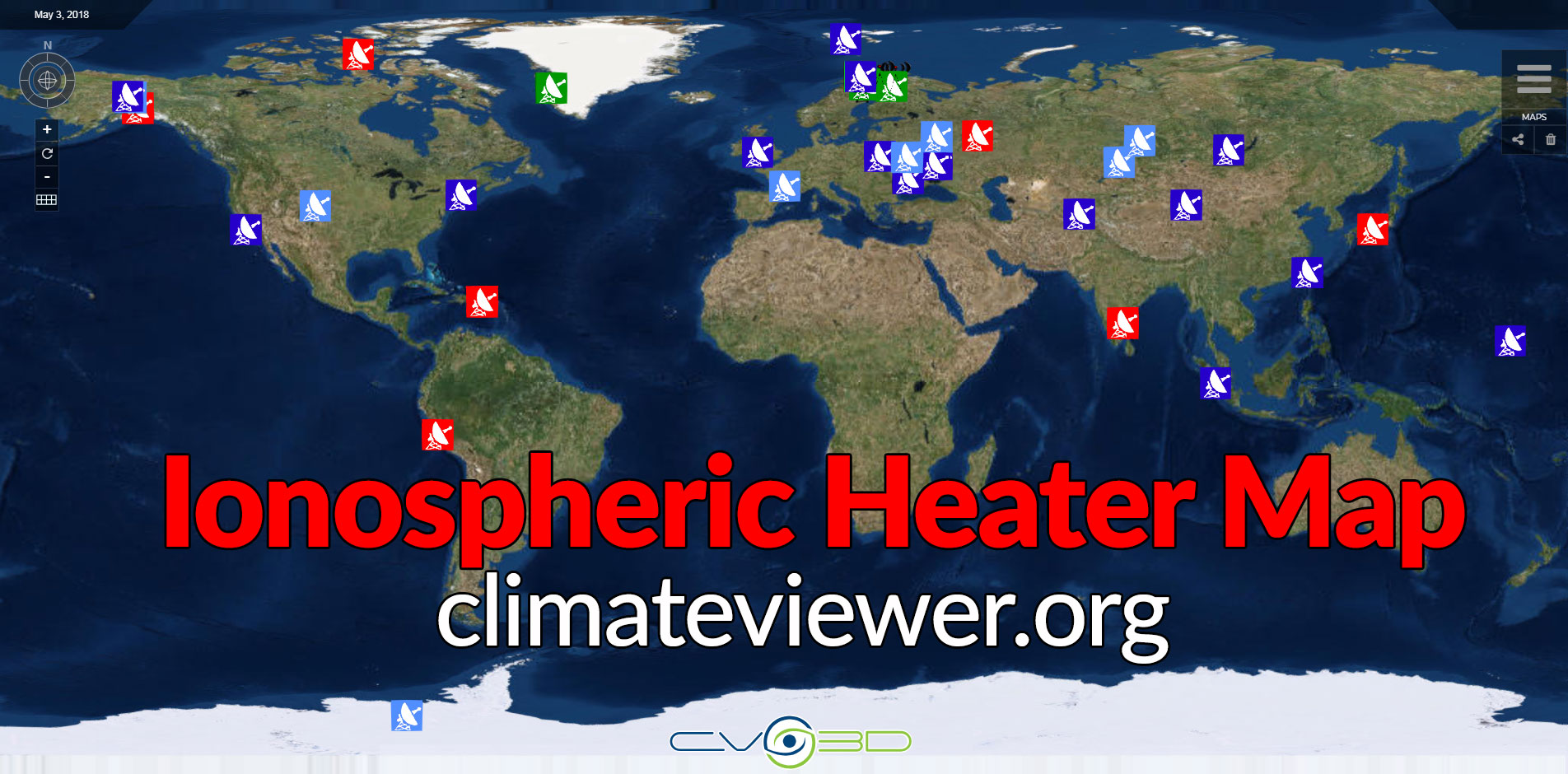
"Powerful HF transmitter (2.8-10 MHz) that induces controlled temporary modification to the electron temperature at desired altitude" which areBasically, scientists are trying to understand our ionosphere by poking it and seeing how it reacts. There are many Ionospheric Heaters around the world, however we will stick to just the top five for the sake of keeping this article short(ish). If you would like to see all of the other Sky Heaters, check out our ClimateViewer Mobile and ClimateViewer 3D HAARP map.“Use(d) in conjunction with diagnostics to study, in a cause and effect fashion: Electromagnetic propagation, plasma turbulence and instabilities” and the
“Response of magnetospheric plasma and Radiation Belts to controlled perturbations (meaning man-made intervention) of the ionospheric plasma”. [1]
Here are the top five Ionospheric Heaters in use today:
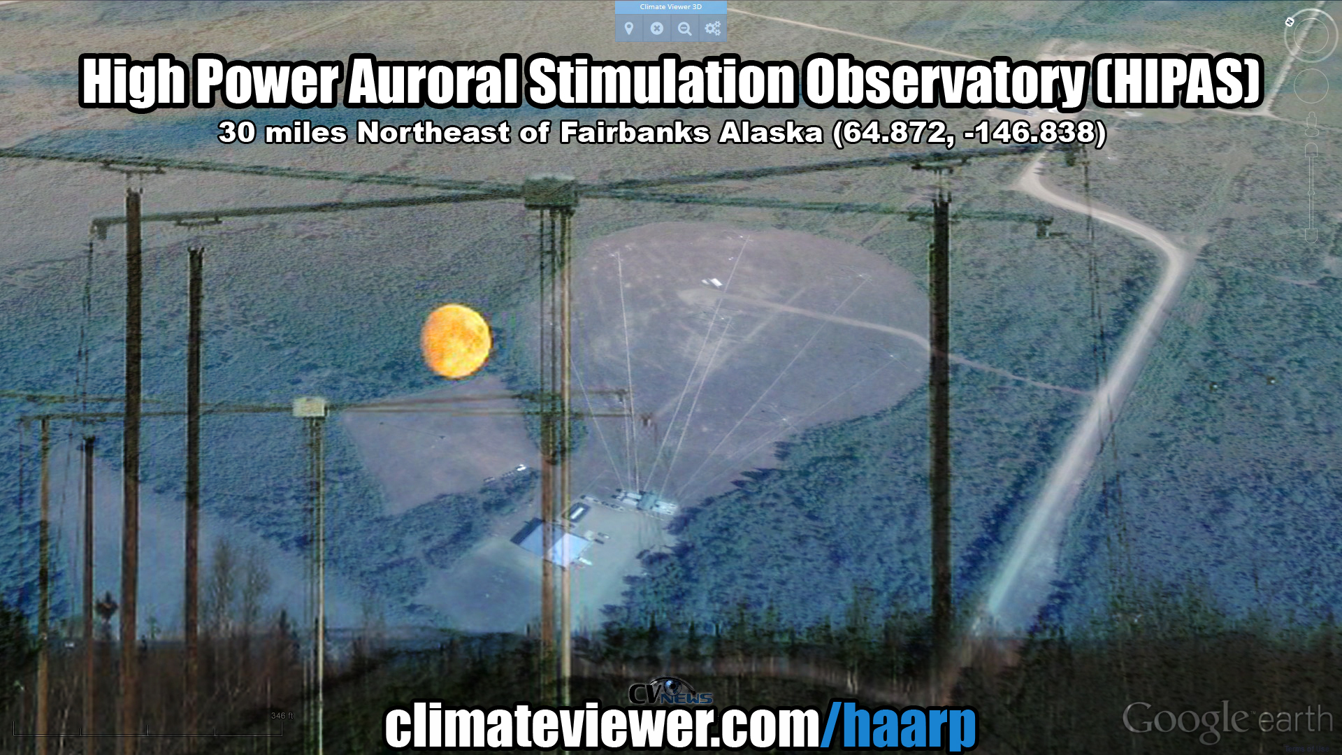
High Power Auroral Stimulation Observatory (HIPAS) [UPDATE** NOW CLOSED 2016]
30 miles Northeast of Fairbanks Alaska 64.87239299272552, -146.8389785512115 http://www.physics.ucla.edu/plasmalab/ http://www.thelivingmoon.com/45jack_files/03files/HIPAS_HIgh_Power_Auroral_Stimulation_Observatory.html- Antennas: circular array of 8 crossed dipoles, copper wire ground-planes and resonant triaxial baluns
- Frequency: 2.85 - 4.53 MHz
- Power: 1,200,000 Watts (1.2 MW, 150 kW x 8)
- ERP: 70,000,000 Watts (70 MW)
The HIPAS facility is engaged in the study of the ionosphere through the use of high power radio transmission as well as a LIDAR (LIght Detection And Ranging ) instrument. The facility is home to several projects with some interesting equipment, including:Some of the research conducted at HIPAS was similar to the controversial HAARP project, and so the staff of the facility sometimes had to answer the same questions from the public. The facility has been shut down and much of the equipment sold off as surplus during the Spring of 2010. [2]
- A plasma torch, used for experiments in hazardous waste disposal
- A 2.8 meter liquid mercury mirror telescope.
- An array of antennae which are used for heating the ionosphere.
The ELF will monitor the resonant frequency of the earth's atmospheric cavity using ground-based receiving coils. The resulting data may provide information about global warming and the nature of earth's atmospheric mantles. Students will be able to excite these waves using the high power transmitter at HIPAS and watch their decay in the earth's resonant cavity. students will learn that a natural system will respond with a larger amplitude when excited at its resonance.ELF waves are of great interest because they resonate with ion cyclotron motion in the Artic atmosphere. CO2- and Cl -. (Ion Dynamics and Ozon, A.Y. Wong 1991. Negative CO2 and Cl ions. [3]
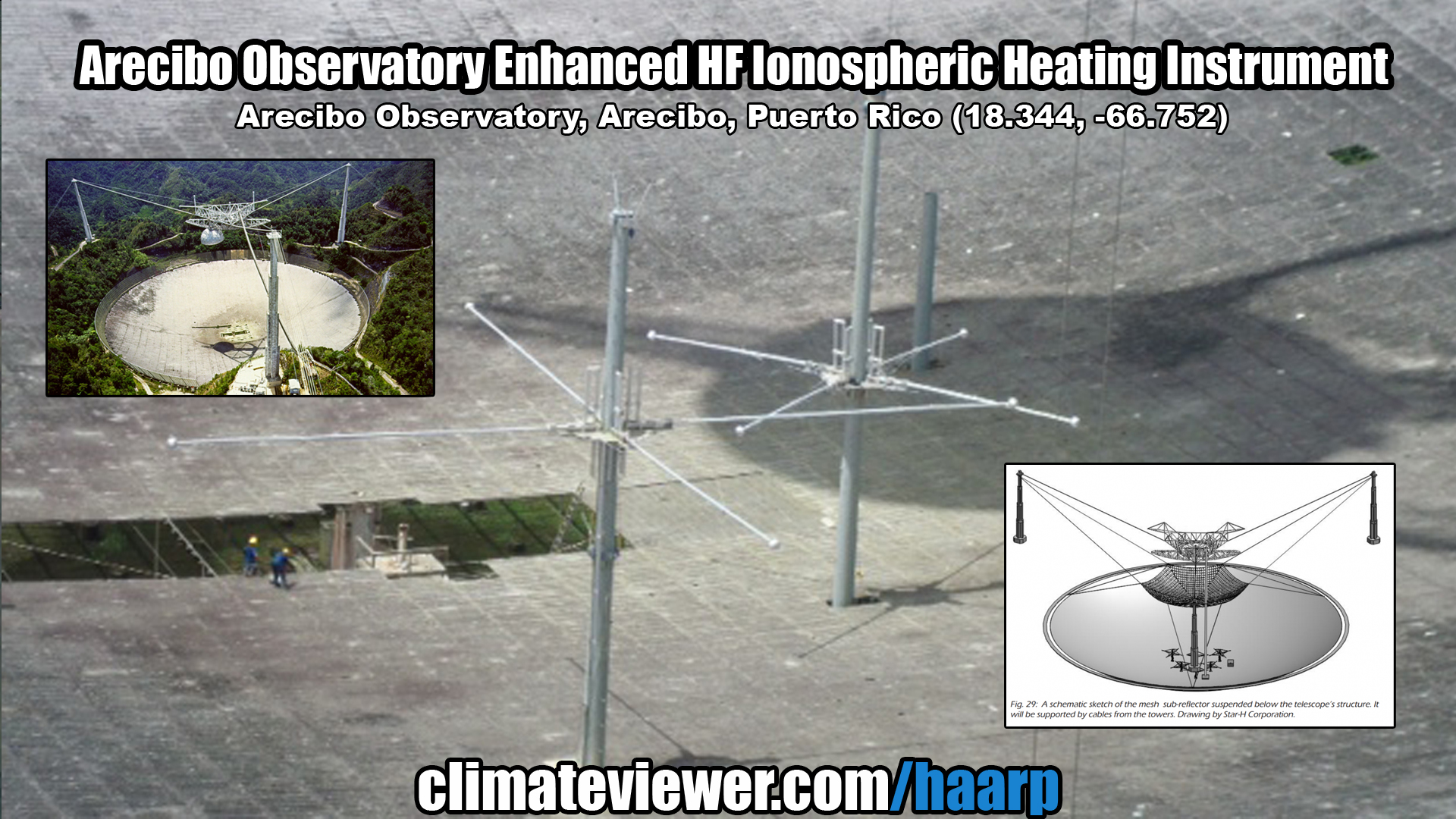
Arecibo Observatory Enhanced HF Ionospheric Heating Instrument
Arecibo Observatory, PR-625, Arecibo, Puerto Rico 18.34421900121537, -66.75269217609858 http://www.naic.edu/- Antennas: 6 crossed dipoles, 5.1 MHz (3 x 25.5 meters) 8.175 MHz (3 x 14.5 meters), 98 meter Cassegrain screen hexagonal sub-reflector, 305 meter dish primary reflector. [4]
- Frequency: 5.1 - 8.175 MHz
- Power: 600,000 Watts (600 kW, 100 kW x 6)
- ERP: 200,000,000 Watts (200 MW)
The investigators will use the enhanced instrument cluster at Arecibo Observatory (AO) to gain new insight into the complex nature of the space-atmosphere interaction region (SAIR). The new High Frequency (HF) heating facility with the ISR (Incoherent Scatter Radar) and other instruments provides a unique opportunity to study heating-related aeronomic and plasma physics problems. This includes the rapidly-imaged observation of airglow at 557.7 nm, 630.0 nm and 427.8 nm during ionospheric "heating" campaigns to understand the role of HF-heating in generating plasma bubbles, or modulating them if already present, and to understand the role of secondary suprathermal electrons in producing airglow at different wavelengths. This research will also yield insight to the heating process, including locating ionospheric "hot-spots", yielding details of the electron collision process, elucidating the role of Langmuir and ion-acoustic waves in the strongly heated regions, and study of heating effects in Sporadic E. The latter study will include Ca+ metal-lidar observations as further defined by 555.7 nm imaging as well as ISR and HF radar results. HF heating of the ionosphere offers a unique opportunity to investigate the plasma heating process and its effects on the neutrals in a controlled (experimental) fashion. Outside of the heating campaigns, a database of 630 nm all-sky camera images from other locations will be assembled collaboratively to investigate the global context of the omnipresent ~1 hr period ionospheric waves, and associated dynamics, first identified with the AO ISR. This work will utilize other AO instruments, including the resonance and Rayleigh lidars, to investigate the role of wave coupling from lower atmospheric regions. Also, a proposed new CCD camera will allow high speed imaging to better understand HF heating effects and linking optical and radar meteors to study meteoroid aeronomy. The response of the SAIR to sudden changes in the environment caused by heating will be explored with the collaborative use of multiple instruments, thus informing numerous geophysical research areas. The multidisciplinary nature of this work will help to establish collaborations with plasma physicists, modelers, and space weather scientists. It will also advance the AO cluster capabilities with the addition of a User-Owned, Public Access (UOPA) high frame rate CCD to the current imager and help in establishing international collaborations. Students representing minorities from local universities in Puerto Rico will be encouraged to participate in observations and data analysis. They will be involved in the improvements of the optical systems including training on AO instrumentation and the application of these instruments to study aeronomy of the SAIR. [5]
The new facility will replace an earlier ionospheric heater in Islote, Puerto Rico, that was destroyed by Hurricane Georges in 1998. Rather than rebuild that installation, the new instrument will use the observatory’s 1000 foot dish for its antenna. This will keep all research activities involving ionospheric modification at the observatory proper.Plans call for a design based on a Cassegrain screen concept of phased array at the bottom of the dish feeding a sub-reflector mesh that hangs above the dish from three support towers. Breakall and his team of graduate students at Penn State have done all of the electrical design and modeling of this new antenna system.
“There are three crossed-dipoles for 5.1 MHz and another three for 8.175 MHz, forming an array that will beam energy up to a net mesh reflector that will hang from the three big towers,” Breakall explained. “This Cassegrain screen will then reflect energy back down to the 1000 foot dish and beam an effective radiated power of hundreds of megawatts up to the ionosphere to modify it.” Each dipole is fed from a 100 kW transmitter, yielding a total transmitted power of 600 kW.
An even earlier HF heating antenna system also was suspended from the platform above the dish and driven by a single 100 kW transmitter over a frequency range of 3 to 10 MHz. That design suffered from arcing problems and was taken out of service in the 1970s. [6]
Sura Ionospheric Heating Facility
Vasilsursk, Nizhny Novgorod Oblast, Russia 56.14360813018452, 46.09902433603985 http://sura.nirfi.sci-nnov.ru/indexe.html (Photo Gallery) http://www.thelivingmoon.com/45jack_files/03files/SURA_Radar_Facility.html- Antennas: 144 crossed dipole, 300 x 300 meters
- Frequency: 4.5 - 9.3 MHz
- Power: 750,000 Watts (750 kW)
- Effective Radiated Power: 190,000,000 Watts (190 MW, ~83 dbW)
The Sura Ionospheric Heating Facility, located near the small town of Vasilsursk about 100 km eastward from Nizhniy Novgorod in Russia, is a laboratory for ionosphere research. Sura is capable of radiating about 190 MW, effective radiated power (ERP) on short waves. This facility is operated by the radiophysical research institute NIRFI in Nizhny Novgorod. The Sura facility was commissioned in 1981. Using this facility, Russian researchers studied the behaviour of the ionosphere and the effect of generation of low-frequency emission on modulation of ionosphere current. In the beginning, the Soviet Defense Department mostly footed the bill. The American HAARP ionospheric heater is similar to the Sura facility. HAARP transmits much lower energy signals in comparison to Sura. The HAARP project began in 1993. [7]

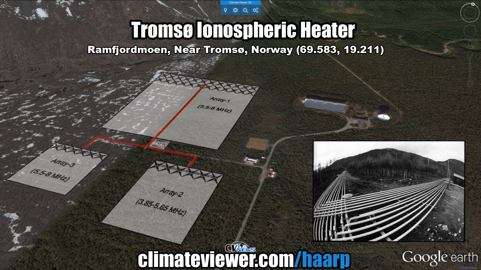
Tromsø Ionospheric Heater
Ramfjordmoen, Near Tromsø, Norway 69.58314833326673, 19.211580995070786 https://www.eiscat.se/about/facilities http://www.thelivingmoon.com/45jack_files/03files/EISCAT_Ramfjordmoen_Tromso_Norway.html- Antennas: 3 arrays
- 144 crossed dipole (12x12), 5.3-8.0 MHz
- 36 crossed dipole (6x6), 3.8-5.7 MHz
- 36 crossed dipole (6x6), 5.3-8.0 MHz
- Frequency: 3.85 - 8 MHz
- Power: 1,200,000 Watts (12 x 100 kW)
- Effective Radiated Power:
- 144 crossed dipole, 1,200,000,000 Watts (1200 MW, 1.2 GW)
- 36 crossed dipole, 300,000,000 Watts (300 MW) [8]
The facility hosts two large incoherent scatter radars (VHF, 224 MHz; UHF, 930 MHz), a Heating facility, a meteor radar, an MF radar, digital ionosondes and optical observatories to investigate the Northern Lights.The immediate purpose of the MORRO radar is the investigation of Polar Mesospheric Summer Echoes (PMSE) and Polar Mesospheric Winter Echoes (PMWE). Of especial interest are dusty plasma physics processes and atmospheric turbulence associated with these echoes. The potential applications of the radar extends well beyond the ability to measure the two mentioned phenomena, a potential that will be exploited in due time, in particular the dynamics, energy budget and coupling of the atmospheric regions, troposphere, stratosphere mesosphere and middle atmosphere.
Of especial interest are the exploitation of the scientific opportunities created by the unique availability of a number of powerful and complementary instruments for the study of the atmosphere, the middle atmosphere and the ionosphere. The Heating facility offers the unique capability to modify the object of investigation, such as PMSE and PMWE, in a controlled manner which enhances considerably the ability to investigate and understand these phenomena and many others. [9]
The HF Heater at Tromsø is getting a huge upgrade:
The core array will comprise a 120-m diameter filled circular aperture array with ≈16 000 elements, laid out on an equilateral triangular grid, and a number (6…9) of smaller outlier receive-only arrays. The core will provide: a half-power beamwidth of ≈ 0.75o, i.e. comparable to that of the EISCAT UHF system, a power-aperture product exceeding 100 GW m2, i.e. an order of magnitude greater than that of the EISCAT VHF system [10]
High Frequency Active Auroral Research Program (HAARP) Ionospheric Research Instrument (IRI)
Gakona, Alaska, USA 62.39234958096403, -145.14912226295115 http://www.haarp.alaska.edu/- Antennas: 180 crossed dipole (12 x 15), 1040' x 1280' (about 30.6 acres)
- Frequency: 2.8 - 10 MHz
- Power: 3,600,000 Watts (3.6 MW)
- Effective Radiated Power: 5,000,000,000 Watts (5 GW)
Basically, the IRI is what is known as a phased array transmitter. It is designed to transmit a narrow beam of high power radio signals in the 2.8 to 10 MHz frequency range. Its antenna is built on a gravel pad having dimensions of 1000' x 1200' (about 33 acres). There are 180 towers, 72' in height mounted on thermopiles spaced 80' apart in a 12 x 15 rectangular grid. Each tower supports near its top, two pairs of crossed dipole antennas, one for the low band (2.8 to 8.3 MHz), the other for the high band (7 to 10 MHz). The antenna system is surrounded by an exclusion fence to prevent possible damage to the antenna towers or harm to large animals. An elevated ground screen, attached to the towers at the 15' level, acts as a reflector for the antenna array while allowing vehicular access underneath to 30 environmentally-controlled transmitter shelters spaced throughout the array. Each shelter contains 6 pairs of 10 kW transmitters, for a total of 6 x 30 x 2 x 10 kW = 3600 kW available for transmission. The transmitters can be switched to drive either the low or high band antennas. Electric prime power is provided from an on-site power plant housing five, 2500 kW generators, each driven by a 3600 hp diesel engine. Four generators are required for operation of the IRI and the fifth is held as a spare. From a control room within the Operations Center, the transmission from each of the 180 crossed-dipole antennas is adjusted in a precise manner under computer control. In this manner, the complete array of antennas forms a narrow antenna pattern pointed upward toward the ionosphere. The transmitted signal diverges (spreads out) as it travels upward and is partially absorbed, at an altitude which depends on the transmitted HF frequency, in a small volume several tens of miles in diameter and a few hundred meters thick directly over the facility. The remainder of the transmitted signal either reflects back toward the earth or passes through the ionosphere into space, continuing to diverge as it does so. By the time it reaches the ionosphere, the intensity of the HF signal is less than 3 microwatts (0.000003 watt) per cm2, thousands of times less than the Sun's natural electromagnetic radiation reaching the earth and hundreds of times less, even, than the variations in intensity of the Sun's natural ultraviolet (UV) energy which creates the ionosphere. [11]

ELF Generation 101
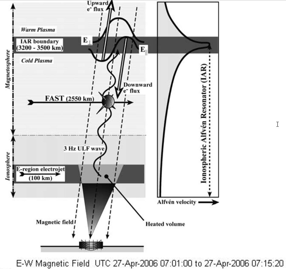
HAARP's IRI creates a "Virtual Antenna" in the sky that radiates extremely low frequency signals that travel worldwide and can be heard in the deepest depths of our oceans.This “Virtual Antenna” is called a Ionospheric Alfven Resonator (IAR). [1]
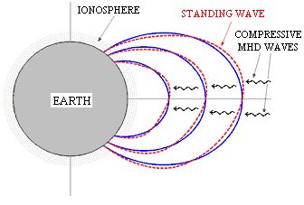
Geomagnetic pulsations are magnetohydrodynamic waves within the Earth’s magnetosphere. They can be of two types: the magnetosonic wave and the Alfven wave. Magnetosonic waves propagate in any direction and generate compressions and rarefactions of both the magnetic field and the plasma; Alfven waves propagate along the direction of the ambient magnetic field and produce magnetic perturbations transversal to the field lines. Compressive MHD waves propagating in the magnetosphere, if their frequency matches the field line eigen frequency, can drive a resonance mechanism. In this situation, standing oscillations of the geomagnetic field lines, which behave as strings with the ends fixed in the ionosphere, occur (Figure 1). [12]
Schematic plot in the meridian plane of compressive MHD waves within the magnetosphere together with transverse standing waves along geomagnetic field lines.The period of geomagnetic pulsations ranges from tenths of seconds to few minutes. As shown in the Table, pulsations are classified, according to their morphological properties, into continuous pulsations (Pc) and irregular pulsations (Pi); within each of these two groups they are further divided according to their period. This classification was proposed by IAGA (International Association for Geomagnetism and Aeronomy) in 1964; it is important however to underline that the frequency values in the different pulsation classes don’t reflect a particular physical meaning, then such a division can be considered just a useful classification scheme. [12]
IAGA classification of geomagnetic pulsations Continuous pulsations Irregolar pulsations Notation Period(s) Frequency(mHz) Notation Period(s) Frequency(mHz) Pc1 0.2 - 5 200 - 5000 Pi1 1 - 40 25 - 1000 Pc2 5 - 10 100 - 200 Pi2 40 - 150 7 - 25 Pc3 10 - 45 22 - 100 Pc4 45 - 150 7 - 22 Pc5 150 - 600 2 - 7
A type of electromagnetic signal propagating in the Earth–ionosphere waveguide, known as a radio atmospheric signal or sferic, may escape the ionosphere and propagate outward into the magnetosphere. The signal is now prone to bounce-mode propagation, reflecting back and forth on opposite sides of the planet until totally attenuated. To clarify which part of this hop pattern the signal is in, it is specified by a number, indicating the portion of the bounce path it is currently on. [14]
![“Virtual ULF/ELF/VLF Ionospheric Antennae” Resolving Critcal Radiaton Belt & Geospace Issues [14]](/2014/10/haarp-sginal-path1.jpg)
Signals are sent into different ionospheric shells depending on the location of the Ionospheric Heater. These are similar to layers in an onion:
Polar Electrojet (PEJ) heating
High-latitude Ionospheric Heaters can use the Electrojet, a naturally occurring electrical current in the D/E Region (70-90 km) of the ionosphere, as both an amplifier and virtual antenna.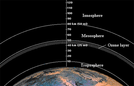
![Forecasting the Auroral Electrojets and Ground-Induced Currents [13]](/2014/10/polar-electrojet1.gif)
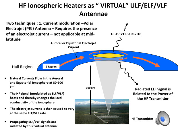
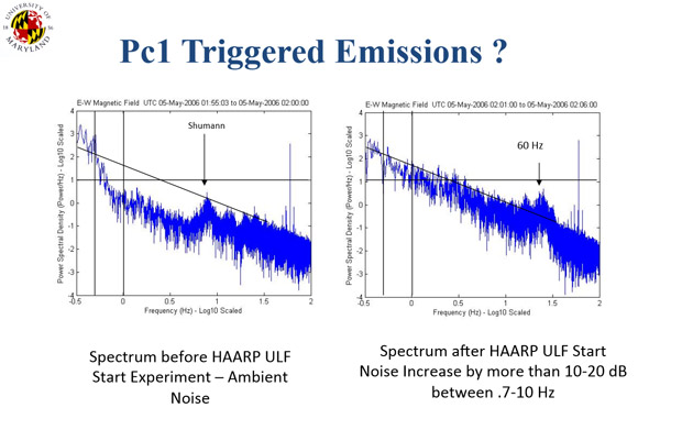
HAARP, HIPAS, and the Tromso are able to use PEJ heating to produce ULF/ELF/VLF from 0.001 Hz - 20,000 Hz (20 kHz) with a 2-8 kHz peak efficiency. [1]
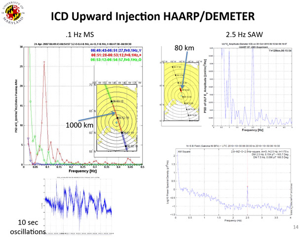
Ionospheric Current Drive (ICD) heating
Both High Latitude and Equatorial Ionospheric Heaters may use an alternate method to produce UFL/ELF waves that does not require the Electrojet. By heating the F layer (150–800 km) of the ionosphere, Magnetosonic (MS) waves are create a secondary Alfven wave generator in the E Region. These Alfven waves travel upward and follow the Van-Allen belts, hopping back and forth.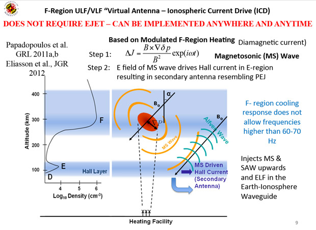
Ionospheric Current Drive (ICD) heating can produce .1 Hz Magnetosonic (MS) waves, 2.5 Hz Shear Alfven Waves (SAW) and ULF/ELF waves up to 50-70 Hz. [1]
Conclusion
Although Ionospheric Heaters have been operational for over 20 years few seem to know about these artificial resonations.Are these electrical alterations to our planet’s protective force-field effecting the nervous systems of life on Earth?
Are Sky Heaters accidentally creating earthquakes?
Could these Electrojet experiments be the cause of “Earth Groans” heard around the globe?
I will attempt to answer these questions and more in the near future. Be sure to catch my next article when we drop a bombshell:
Ionospheric Heaters on trailers? Heaters on submarines? Heaters on boats? The truth is coming, stay tuned.
(Questions/comments/concerns Hit me up on skype: rezn8d or any of my social media)
References
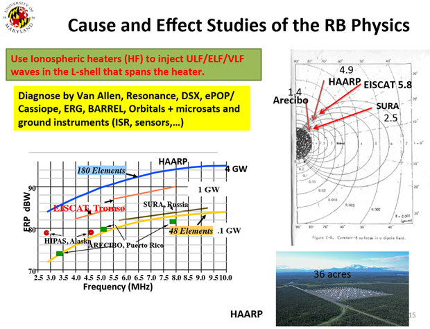
- http://spp.astro.umd.edu/SpaceWebProj/Invited%20Talks/Active%20Experiments-2013.pdf – Using Active Experiments to Probe Geospace, Dennis Papadopoulos, University of Maryland
- http://en.wikipedia.org/wiki/HIPAS_Observatory - High Power Auroral Stimulation Observatory (HIPAS), Wikipedia
- http://www.physics.ucla.edu/plasmalab/elf.html - ELF generation, UCLA Physics Plasma Lab
- http://www.ee.psu.edu/Newsletters/January.pdf - Penn State Researchers Near Completion of Project for Arecibo Observatory, January 2010
- http://grantome.com/grant/NSF/AGS-1241436 - Collaborative Research: New Directions in Optical-Instrument-Driven Aeronomy at Arecibo Observatory
- http://www.arrl.org/news/haarp-like-ionospheric-research-project-underway-at-arecibo-observatory - HAARP-Like Ionospheric Research Project Underway at Arecibo Observatory
- http://en.wikipedia.org/wiki/Sura_Ionospheric_Heating_Facility - Sura Ionospheric Heating Facility, Wikipedia
- http://www.eiscat.uit.no/heater.html - EISCAT's ionospheric Heating facility including Dynasonde
- http://tupac.phys.uit.no/~cesar/MORROradarSite/MORROradar.html - MORRO MST (Mesosphere-Stratosphere-Troposphere) Radar, Tromso EISCAT
- https://web.archive.org/web/20100817202724/http://www.eiscat.se/groups/EISCAT_3D_info/Final_Report_Activity_Report_EU-Style.pdf Project Final Report EISCAT_3D European Next Generation Incoherent Scatter Radar
- https://web.archive.org/web/http://www.haarp.alaska.edu/haarp/factSheet.html - HAARP Fact Sheet
- http://roma2.rm.ingv.it/en/themes/22/magnetic_pulsations - Magnetic Pulsations, Istituto Nazionale di Geofisica e Vulcanologia, Roma2 Department: Geomagnetism, Aeronomy and Environmental Geophysics
- https://engineering.dartmouth.edu/spacescience/wl/res/ae/ - Forecasting the Auroral Electrojets and Ground-Induced Currents
- http://en.wikipedia.org/wiki/Whistler_(radio) - Whistler wave, Wikipedia
- http://spp.astro.umd.edu/SpaceWebProj/Invited%20Talks/Virtual%20ULF%20Antennea-2013.pdf – “Virtual ULF/ELF/VLF Ionospheric Antennae” Resolving Critcal Radiaton Belt & Geospace Issues, Dennis Papadopoulos, University of Maryland
This article is part of the series: HAARP and the Sky Heaters
Also check out WeatherModificationHistory.com

“I am forever a Boy Scout, lifetime artist, nocturnal programmer, music is my life, love is my religion, and I am the luckiest husband and father on Earth. I speak for the trees. I have a passion for mapping, magnets, and mysteries.”
About Jim Lee")